Water Cooler Pump Wiring Diagram
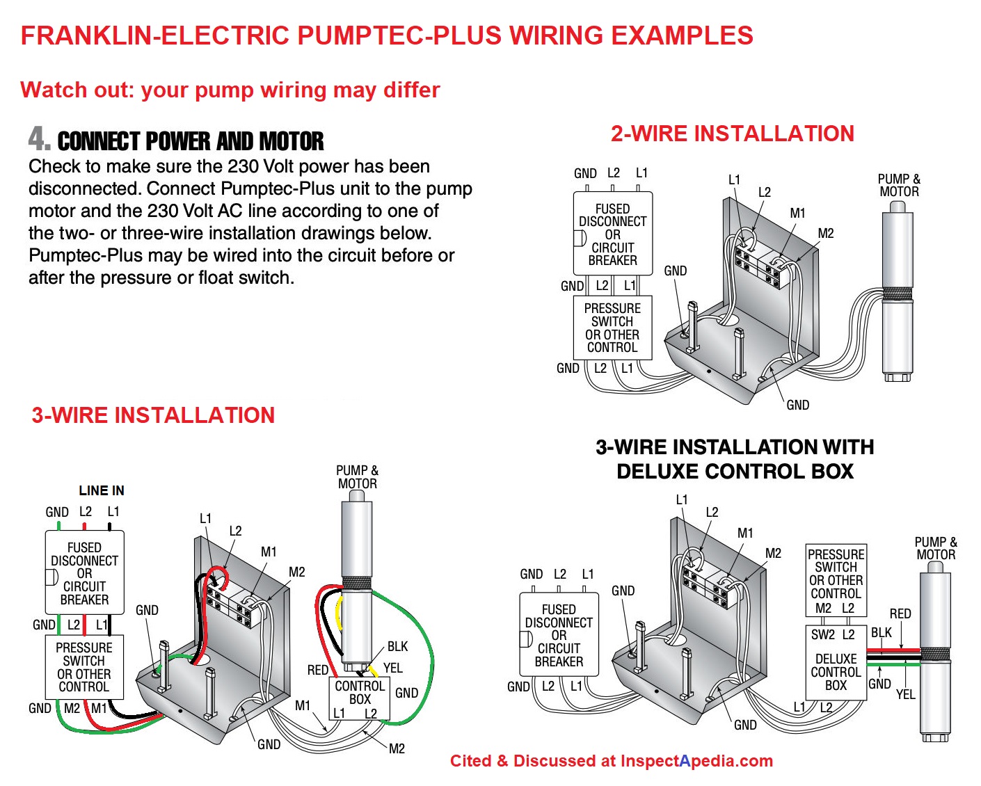
Locate the wiring diagram for your injection kit further in these instructions beginning. Submersible pump control box wiring diagram for 3 wire single phase submersible pump submersible well.

Wiring Diagram For Water Pump Motor
Evaporative cooling (residential) switches and wiring are on the left of the diagram, wiring to the unit on the roof is on the right side of the diagram.

Water cooler pump wiring diagram. The reservoir should be installed above the pump, but below the nozzle. To be wired inaccordance with n.e.c.and local codes. Cover in dishwasher or wipe parts clean with a soft cloth and warm soapy.
The other end of the black wire is connected to the switch. Use copper wire (75ºc min) only between disconnect switch and unit. Water cooled engine diagram free electrical diagram water cooler mechanic engineering circuit diagram for kenlowe cooling fan.
1/4 pex may also be used, but takes special tools to prepare the joints. Follow the subsequent electrical wiring diagram/instructions. This motor must be grounded by attaching the power supply green ground wire to the motor electrical power source.
Compressor oil cooler great water, inc. Using preferred electrical fitting connect white wire to pump red power wire. Plug 2 1 schematic diagram 1.
Locate the wiring diagram for your injection kit further in these instructions beginning. This dispenser is intended for water dispensing only. Water cooler pump wiring wall switch for 2 speed evaporative coolers it helps control a variety of functions on your 2 speed cooler this 6 position rotary switch can be used with 1 3 to 3 4 hp motors thd sku 715166, room air cooler wiring diagram 1 note check
Primo water pump user manual catchy dispenser parts superb primo water cooler wiring diagram troubleshooting rh ez info model. Water cooler pump wiring operation manual water cooler en diagenode, pc water cooling pumps ek webshop, ajanta cooler water pump 50hz 220v color may vary, free download here pdfsdocuments2 com, room air cooler wiring diagram 1 electrical technology, how do you wire the mastercool evaporative cooler to the, portable evaporative air Motor and pump have a grounded, molded plug and an automatic
Purple on controller to either wire on level sensor for tank. Cooler pump installation kit is rated 3 0 out of 5 by 5 rated 4 out of 5 by homedepotcustomer from 4 star review rating provided by a verified purchaser date published 2019 02 06 rated submersible water pump replacement for evaporative cooler models mbc2000 mc21, water cooler wiring diagram wiring diagram of refrigerator and water cooler nkjskj Green on controller to red on pump.
Svb century i tried to connect the. Is video me aap cooler pump ke connection or cooler pump repairing ke baare me jaanengewater level controller for submersible starter or dol starter videohtt. Room air cooler wiring diagram 1 room air cooler wiring diagram 1 note check the room air.
14 maine street, box 34, brunswick, me 04011 tel: Green = ground blue = run brown = start black = common you will see that Ifany of the original wire,as supplied, must be replaced, use the same or equivalent type wire.
2 speed swamp cooler motor wiring diagram. See the following wiring diagrams for 120v and 240v installations. The tilton oil cooler pump is placed inline with the cooling system as shown in diagram 1.
Your cooler will run on either 120v or 240v a.c., single phase, 60 hz (cycle) current. Do not use keep water dispenser in a dry place away from direct sunlight. On primo water cooler parts diagram.
Tape off end of both of the red leads. It was purchased in 1994 or 19. Placing the pump on the outlet side of the cooler exposes it to lower temperatures significantly increasing the life and reliability of the pump.
I have a swamp cooler with a 2 speed motor: When a single speed motor is used, do not use the red lead on the receptacle and motor plug wiring. On the cooler side, the black wire connects to the blower motor via a junction.
Room air cooler wiring diagram # 2 (with capacitor marking and installation) room air cooler wiring diagram # 1. Always turn off power and unplug motor and pump inside the cooler before installing or performing any maintenance. Check the room air cooler wiring diagram # 2.
2 less than a minute. Room air cooler wiring diagram # 1. So that all electrical wiring will conform to your local codes.
240v pump operation, a 240v pump must be purchased. Wiring diagram of refrigerator and water cooler water cooler electrical circuit diagram ac circuit room air cooler wiring diagram 2 with capacitor marking and installation electrical technology room air cooler air cooler room cooler pin on ceiling fan wiring diagram cooler motor connection cooler motor connection with capacitor cooler repair repair cooler. Aquanation bpa free replacement cooler faucet water bottle jug reusable spigot spout water beverage lever pour dispenser.
Must be suitable for your cooler size. Use 1/4 copper (preferable) or 1/4 plastic tubing.
Air Room Water Cooler Wiring Diagram

2003NissanQuestEngineDiagram RAUR.US

ThreeWay Switch Wiring How to Wire 3Way Switches

Wiring Diagram For Water Pump Motor Irish Connections

Ro Electrical Connection Diagram Wiringpedia

Electrical Wiring Diagram For Water Pump Motor Set Irish
Columbia Boiler Piping Diagram School Cool Electrical

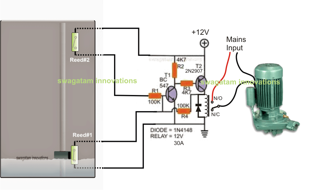
Automatic Water Level Controller Wiring Diagram For 3

12v Water Pump Wiring Diagram arjunariyanti

2003NissanQuestEngineDiagram RAUR.US

Mechanical & Marine Systems Engineering Walkin cooler

Thermostat Wiring Diagram 2 Wire at Wiring
Wiring Diagram For Water Cooler Water Dispenser Diagram

Pentair Superflo 1.5 Hp Wiring Diagram Collection

2003NissanQuestEngineDiagram RAUR.US
Custom PC Water Cooling LabJack

Smart Programmable Heat Pump with Emergency or Auxiliary


